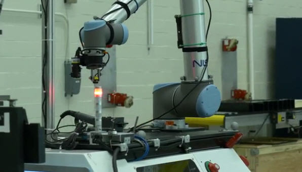
New standard helps optical trackers follow moving objects precisely

Video: In this segment of the "NIST in 90" series, host Chad Boutin and NIST engineer Roger Bostelman demonstrate why it's important to evaluate how well optical tracking systems can place an object, such as a mobile robot in a factory, in 3-D space. Credit: NIST
To make that measurement more reliable, a public-private team led by the National Institute of Standards and Technology (NIST) has created a new standard test method to evaluate how well an optical tracking system can define an object's position and orientation–known as its “pose”–with six degrees of freedom: up/down, right/left, forward/backward, pitch, yaw and roll.
Optical tracking systems work on a principle similar to the stereoscopic vision of a human. A person's two eyes work together to simultaneously take in their surroundings and tell the brain exactly where all of the people and objects within that space are located.
In an optical tracking system, the “eyes” consist of two or more cameras that record the room and are partnered with beam emitters that bounce a signal–infrared, laser or LIDAR (Light Detection and Ranging)–off objects in the area. With both data sources feeding into a computer, the room and its contents can be virtually recreated.
Determining the pose of an object is relatively easy if it doesn't move, and previous performance tests for optical tracking systems relied solely on static measurements. However, for systems such as those used to pilot automated guided vehicle (AGV) forklifts–the robotic beasts of burden found in many factories and warehouses–that isn't good enough. Their “vision” must be 20/20 for both stationary and moving objects to ensure they work efficiently and safely.
To address this need, a recently approved ASTM International standard (ASTM E3064-16) now provides a standard test method for evaluating the performance of optical tracking systems that measure pose in six degrees of freedom for static–and for the first time, dynamic–objects.
NIST engineers helped develop both the tools and procedure used in the new standard. “The tools are two barbell-like artifacts for the optical tracking systems to locate during the test,” said NIST electronics engineer Roger Bostelman. “Both artifacts have a 300-millimeter bar at the center, but one has six reflective markers attached to each end while the other has two 3-D shapes called cuboctahedrons [a solid with 8 triangular faces and 6 square faces].” Optical tracking systems can measure the full poses of both targets.
According to Bostelman's colleague, NIST computer scientist Tsai Hong, the test is conducted by having the evaluator walk two defined paths–one up and down the test area and the other from left and right–with each artifact. Moving an artifact along the course orients it for the X-, Y- and Z-axis measurements, while turning it three ways relative to the path provides the pitch, yaw and roll aspects.
“Our test bed at NIST's Gaithersburg, Maryland, headquarters has 12 cameras with infrared emitters stationed around the room, so we can track the artifact throughout the run and determine its pose at multiple points,” Hong said. “And since we know that the reflective markers or the irregular shapes on the artifacts are fixed at 300 millimeters apart, we can calculate and compare with extreme precision the measured distance between those poses.”
Bostelman said that the new standard can evaluate the ability of an optical tracking system to locate things in 3-D space with unprecedented accuracy. “We found that the margin of error is 0.02 millimeters for assessing static performance and 0.2 millimeters for dynamic performance,” he said.
Along with robotics, optical tracking systems are at the heart of a variety of applications including virtual reality in flight/medical/industrial training, the motion capture process in film production and image-guided surgical tools.
“The new standard provides a common set of metrics and a reliable, easily implemented procedure that assesses how well optical trackers work in any situation,” Hong said.
The E3064-16 standard test method was developed by the ASTM Subcommittee E57.02 on Test Methods, a group with representatives from various stakeholders, including manufacturers of optical tracking systems, research laboratories and industrial companies.
###
The E3064-16 document detailing construction of the artifacts, setup of the test course, formulas for deriving pose measurement error and the procedure for conducting the evaluation may be found on the ASTM website, http://www.
Media Contact
All latest news from the category: Information Technology
Here you can find a summary of innovations in the fields of information and data processing and up-to-date developments on IT equipment and hardware.
This area covers topics such as IT services, IT architectures, IT management and telecommunications.
Newest articles

First-of-its-kind study uses remote sensing to monitor plastic debris in rivers and lakes
Remote sensing creates a cost-effective solution to monitoring plastic pollution. A first-of-its-kind study from researchers at the University of Minnesota Twin Cities shows how remote sensing can help monitor and…

Laser-based artificial neuron mimics nerve cell functions at lightning speed
With a processing speed a billion times faster than nature, chip-based laser neuron could help advance AI tasks such as pattern recognition and sequence prediction. Researchers have developed a laser-based…

Optimising the processing of plastic waste
Just one look in the yellow bin reveals a colourful jumble of different types of plastic. However, the purer and more uniform plastic waste is, the easier it is to…


